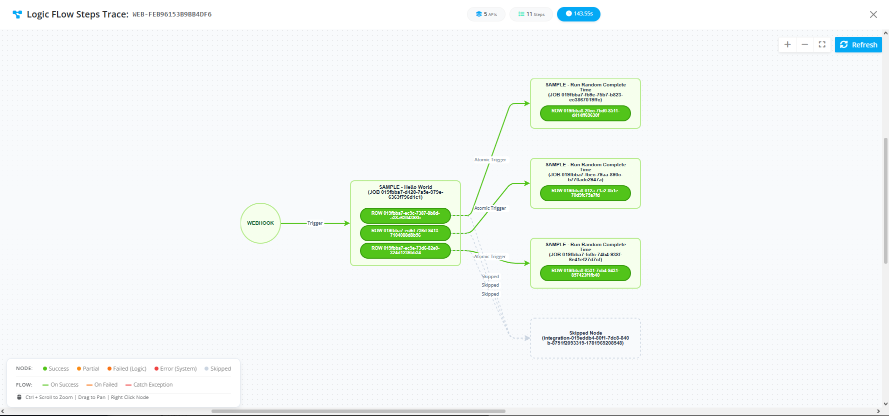
Visual Process Automation (Batch & Atomic Fan-Out)
Overview
This use case demonstrates MdlWr's advanced Visual Process Automation capabilities, specifically highlighting how asynchronous jobs handle bulk data items.
In enterprise workflows, a single incoming payload often contains multiple records (an array of items). MdlWr allows you to process these items flexibly through connected nodes:
- Batch Mode (1 Job Triggers 1 Job): Bundles all items together and passes them downstream as a single array payload.
- Atomic Mode (1 Row Triggers 1 Job / Fan-Out): Automatically splits (fans out) the array, spawning an individual, independent asynchronous job for every single row/item.
Prerequisites & Architecture Workflow
[ Incoming Payload (Array of Items) ]
│
▼
[ MdlWr Async Job ]
│
├── (Option A: Batch Mode) ──> Sends entire array as 1 bundled payload to Next Job
│
└── (Option B: Atomic Mode) ──> Fans out into N separate jobs for each individual row/item
│
├── Item 1 ──> [ Node 1: Hello World ] ──> [ Node 2: Random Complete Time ]
├── Item 2 ──> [ Node 1: Hello World ] ──> [ Node 2: Random Complete Time ]
└── Item N ──> [ Node 1: Hello World ] ──> [ Node 2: Random Complete Time ]
Follow the step-by-step implementation guide below to configure and test batch and atomic processing flows within the platform.
Step-by-Step Implementation Guide
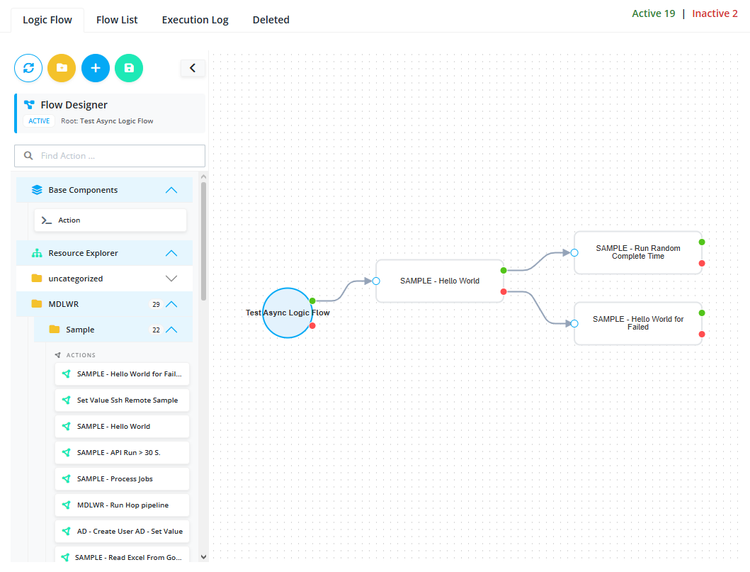
Step 1: Create a New Logic Flow
Set up the foundational asynchronous workflow to receive bulk data payloads.
- Navigate to Integration > Logic Flows.
- Create a new logic flow and configure its processing mode to Async and execution mode to Webhook.
- Fill in required metadata such as Name, Path, and Category, then save.
Step 2: Add Initial API Node (Hello World)
Incorporate the first processing block into your visual pipeline.
- Open the logic flow visual canvas/editor.
- Drag and drop the built-in sample API node:
MDLWR > Sample > Sample - Hello World.
Step 3: Add Subsequent API Node (Random Complete Time)
Incorporate the next step in the pipeline that will receive data from the previous node.
- Drag and drop the second sample API node:
MDLWR > Sample > SAMPLE - Run Random Complete Time.
Step 4: Connect the Nodes
Establish the execution pipeline path.
- Connect the output of the Hello World node to the input of the Random Complete Time node.
- Ensure the connection is tied to the Success execution branch.
Step 5: Configure Connection Logic (Batch vs. Atomic)
Determine how data passes from one node to the next by editing the connector rules.
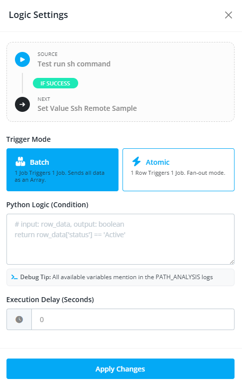
- Right-click on the connecting line between the two nodes.
- Select Edit Logic from the context menu.
-
Choose your preferred processing mode:
- Batch Mode: Select
1 Job Triggers 1 Job. This bundles and sends all incoming data items downstream as a single array. - Atomic Mode: Select
1 Row Triggers 1 Job. This activates Fan-out mode, breaking the array down so every individual row triggers its own isolated downstream job.
- Batch Mode: Select
Step 6: Apply Python Filtering Logic (Optional)
Add conditional execution rules to filter rows dynamically during processing.
- Within the connection logic settings, insert custom Python evaluation code if needed.
- For example, use a condition like
return row_data['status'] == 'Active'to ensure only matching rows proceed to the next node. - Save the connection configuration.
Step 7: Save the Logic Flow
- Click Submit to store the complete visual process flow configuration.
Testing via Flow Tester
Verify how your batch or atomic fan-out logic behaves under live payload conditions.
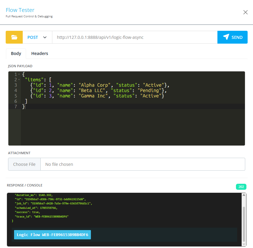
- Navigate to System > Flow Tester.
- Select your newly created visual process automation flow using the folder browser.
- Provide a test payload structured as an array of items (e.g., simulating multiple user or transaction records):
{
 "items": [
   {"id": 1, "name": "Alpha Corp", "status": "Active"},
   {"id": 2, "name": "Beta LLC", "status": "Pending"},
   {"id": 3, "name": "Gamma Inc", "status": "Active"}
 ]
}